Operating System(OS) Preparation for Interviews

India
What is an operating system?
An operating system is a program that acts as an interface between the user and the computer hardware and controls the execution of all kinds of programs.
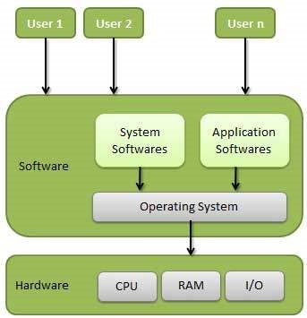
Following are some of the important functions of an operating System.
- Memory Management
- Processor Management
- Device Management
- File Management
- Security
- Control over system performance
- Job Accounting
- Error detecting aids
- Coordination between other software and users
Memory management
Memory management refers to the management of Primary Memory or Main Memory. An Operating System does the following activities for memory management −
- Keeps tracks of primary memory, i.e., what part of it is in use by whom, and what part is not in use.
- In multiprogramming, the OS decides which process will get memory when and how much.
- Allocates the memory when a process requests it to do so.
- De-allocates the memory when a process no longer needs it or has been terminated.
Processor management
In a multiprogramming environment, the OS decides which process gets the processor when and for how much time. This function is called process scheduling. An Operating System does the following activities for processor management −
- Keeps track of processor and status of processes. The program responsible for this task is known as the traffic controller.
- Allocates the processor (CPU) to a process.
- De-allocates processor when a process is no longer required.
Device Management
An Operating System manages device communication via their respective drivers. It does the following activities for device management −
- Keeps track of all devices. The program responsible for this task is known as the I/O controller.
- Decides which process gets the device when and for how much time.
- Allocates the device in an efficient way.
- De-allocates devices.
File Management
A file system is normally organized into directories for easy navigation and usage. These directories may contain files and other directions. An Operating System does the following activities for file management −
- Keeps track of information, location, uses, status, etc. The collective facilities are often known as the file system.
- Decides who gets the resources.
- Allocates the resources.
- De-allocates the resources.
Security
By means of passwords and similar other techniques, it prevents unauthorized access to programs and data.
Control over system performance
Recording delays between request for a service and response from the system.
Job accounting
Keeping track of time and resources used by various jobs and users.
Error detecting aids
Production of dumps, traces, error messages, and other debugging and error detecting aids.
Coordination between other software and users
Coordination and assignment of compilers, interpreters, assemblers, and other software to the various users of the computer systems.
Types of operating systems
Batch OS
Users using batch operating systems do not interact directly with the computer. Each user prepares their job using an offline device like a punch card and submitting it to the computer operator. Jobs with similar requirements are grouped and executed as a group to speed up processing. Once the programmers have left their programs with the operator, they sort the programs with similar needs into batches.
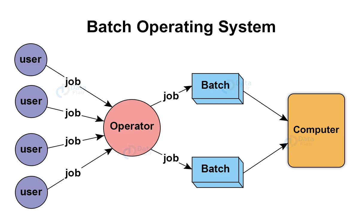
All jobs are executed in the “First Come First Serve” nature.
Examples: Payroll System, Bank Invoice System, Daily Report, Research Segment, Billing System, etc.
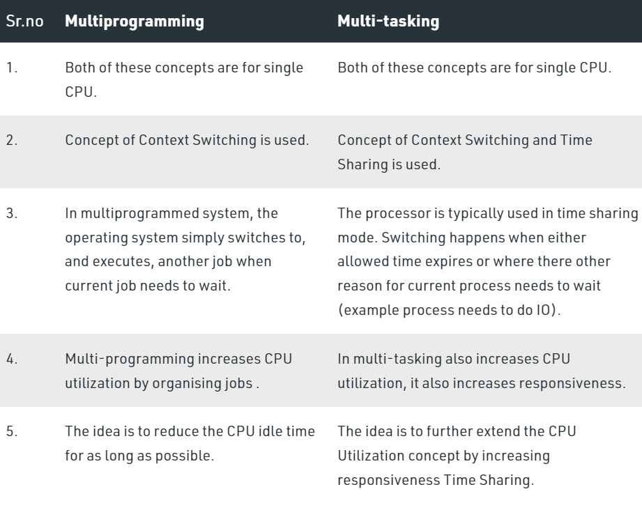
Multiprogramming OS
Performing multiple programs
Non-preemptive
The main memory consists of jobs waiting for CPU time. The OS selects one of the processes and assigns it to the CPU. Whenever the executing process needs to wait for any other operation (like I/O), the OS selects another process from the job queue and assigns it to the CPU. This way, the CPU is never kept idle and the user gets the flavor of getting multiple tasks done at once.
Multitasking OS
Preemptive
Time-sharing OS
Multitasking is the ability of an OS to execute more than one task simultaneously on a CPU machine. These multiple tasks share common resources (like CPU and memory). In multi-tasking systems, the CPU executes multiple jobs by switching among them typically using a small time quantum, and the switches occur so quickly that the users feel like interact with each executing task at the same time.
High response time
Real time OS
Real-time operating systems (RTOS) are used in environments where a large number of events, mostly external to the computer system, must be accepted and processed in a short time or within certain deadlines. such applications are industrial control, telephone switching equipment, flight control, and real-time simulations. With an RTOS, the processing time is measured in tenths of seconds. This system is time-bound and has a fixed deadline. The processing in this type of system must occur within the specified constraints. Otherwise, This will lead to system failure.
Examples of real time operating systems: Airline traffic control systems, Command Control Systems, Airlines reservation systems, Heart Pacemaker, Network Multimedia Systems, Robot, etc.
Distributed OS
A distributed operating system is system software over a collection of independent software, networked, communicating, and physically separate computational nodes. They handle jobs that are serviced by multiple CPUs. Each individual node holds a specific software subset of the global aggregate operating system.
Fault tolerance and scalable.
Clustered OS
Clustered systems are made up of two or more independent systems linked together. They have independent computer systems and shared storage media, and all systems work together to complete all tasks.
Fault tolerance and scalable.
Embedded OS
The main goal of designing an embedded operating system is to perform specified tasks for non-computer devices. It allows the executing programming codes that deliver access to devices to complete their jobs. Ex- Operating system for washing machine, microwave, etc.
Process states
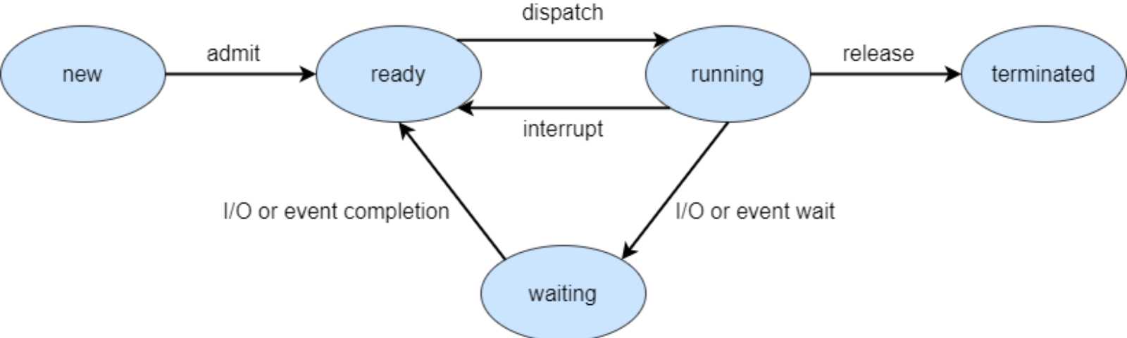
New - State when the process has just been created.
Ready - In the ready state, the process is waiting to be assigned to the processor so it can run.
Running - State when the process instructions are being executed by the processor.
Terminated - Process is terminated once it finishes its execution. In the terminated state, the process is removed from the main memory and its process control block is also deleted.
Wait - The process is waiting until an event occurs like I/O operation completion or receiving a signal.
System call in OS
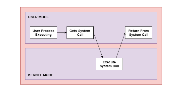
User mode and kernel mode in OS
The interface between a process and an operating system is provided by system calls. System calls are usually made when a process in user mode requires access to a resource. Then it requests the kernel to provide the resource via a system call.
Ex - printf() statement in your code requires output on the monitor then it needs access to your monitor screen. This happens through system calls.
Types of system calls
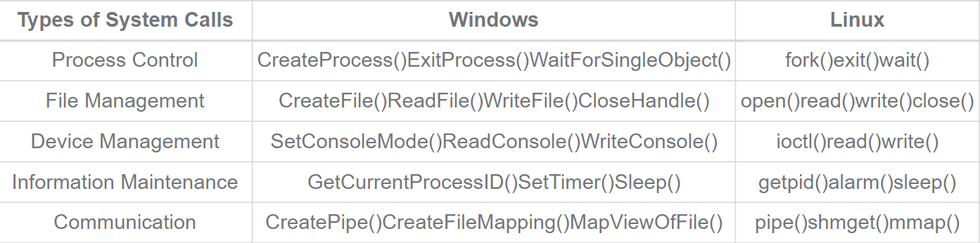
Fork system call - Create a child process from the parent process.
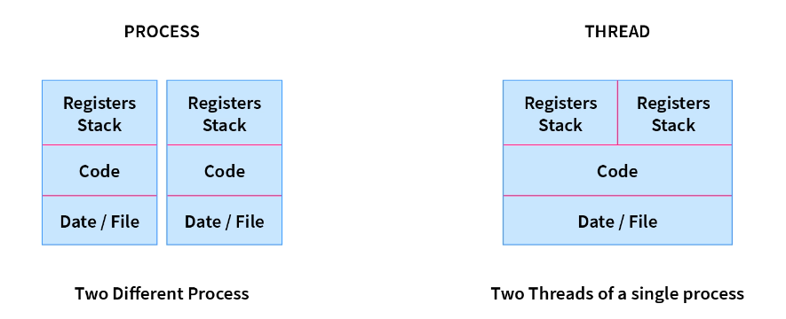
Process and Threads
A thread is a lightweight process and forms the basic unit of CPU utilization. A process can perform more than one task at the same time by including multiple threads.
Eg: While playing a movie on a device the audio and video are controlled by different threads in the background.
- A thread has its own program counter, register set, and stack
- A thread shares resources with other threads of the same process the code section, the data section, files, and signals.
- A new thread, or a child process of a given process, can be introduced by using the fork() system call. A process with n fork() system calls generates 2^n – 1 child processes.
Multithreading
In Multithreading, the idea is to divide a single process into multiple threads instead of creating a whole new process.
Advantages - Resource Sharing and Responsiveness
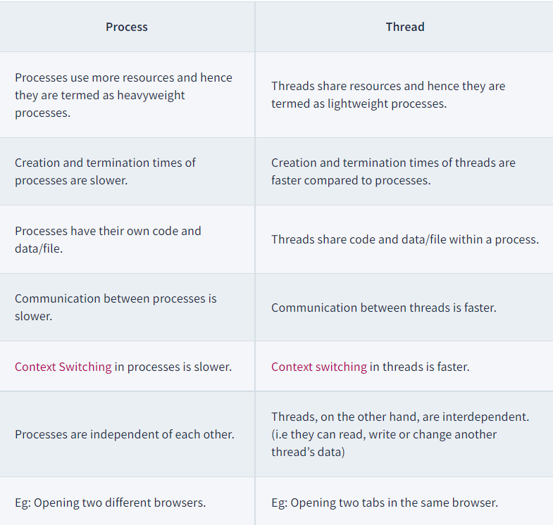
Process vs threads
User level threads vs kernel level threads
User Level Thread:
- User-level threads are implemented and managed by the user and the kernel is not aware of it.
- User-level threads are implemented using user-level libraries and the OS does not recognize these threads.
- User-level thread is faster to create and manage compared to a kernel-level thread.
- Context switching in user-level threads is faster.
- If one user-level thread performs a blocking operation then the entire process gets blocked. Eg: POSIX threads, Java threads, etc.
Kernel level Thread:
- Kernel level threads are implemented and managed by the OS.
- Kernel level threads are implemented using system calls and Kernel level threads are recognized by the OS.
- Kernel-level threads are slower to create and manage compared to user-level threads.
- Context switching in a kernel-level thread is slower.
- Even if one kernel-level thread performs a blocking operation, it does not affect other threads. Eg: Window Solaris.
Process scheduling
Process scheduling is the activity of the process manager that handles the removal of the running process from the CPU and the selection of another process on the basis of a particular strategy.
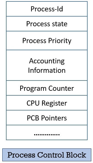
Process control block-
Process Control Block is a data structure that contains information about the process related to it. It also defines the current state of the operating system.
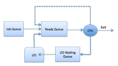
Scheduling queues-
A ready queue keeps a set of all processes residing in the main memory, ready and waiting to execute. A new process is always put in this queue.
Active processes are placed in a running queue.
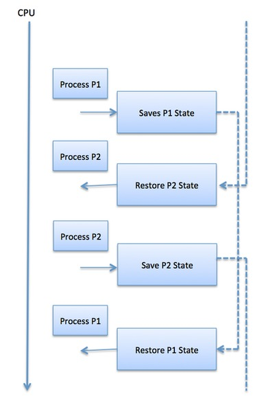
Context switching-
When the scheduler switches the CPU from executing one process to executing another, the state from the currently running process is stored in the process control block. After this, the state for the process to run next is loaded from its own PCB and used to set the PC, registers, etc. At that point, the second process can start executing.
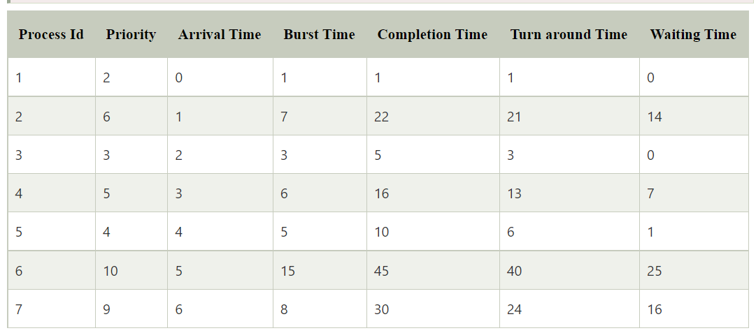
Times in CPU scheduling
- Arrival Time: The time at which the process arrives in the ready queue.
- Completion Time: The time at which process completes its execution.
- Burst Time: Time required by a process for CPU execution.
- Turn Around Time: Time Difference between completion time and arrival time.
Turn Around Time = Completion Time - Arrival Time
- Waiting Time (WT): Time Difference between turn around time and burst time.
Waiting Time = Turn Around Time - Burst Time
- Response Time: Time difference between time at which process gets CPU and arrival time.
First come first serve (FCFS)
Non-preemptive
Criteria: Arrival time
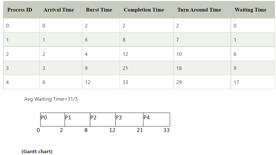
Low response time
Leads to convoy effect
Average wait time is high
Shortest job first (SJF)
Non-preemptive
Criteria: Burst time (If burst time is same, select on basis of arrival time)
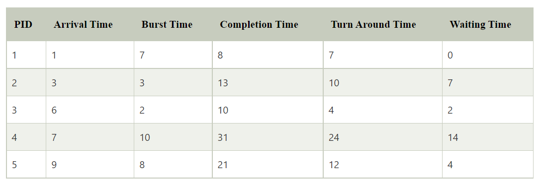
May lead to starvation as if shorter processes keep on coming, then longer processes will never get a chance to run.
Time taken by a process must be known to the CPU beforehand, which is not always possible.
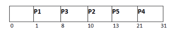
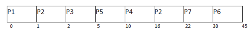
Shortest remaining time first (SRTF)
Preemptive
Criteria: Burst time (If burst time is same, select on basis of arrival time)
Processes are executed faster than SJF, being the preemptive version of it.
Context switching is done a lot more times and adds to the more overhead time.
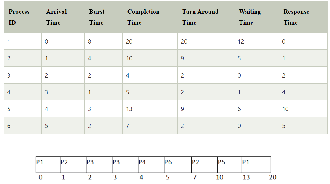
Round robin scheduling
Preemptive
Criteria: Time quantum
All processes are given the same priority; hence all processes get an equal share of the CPU.
Since it is cyclic in nature, no process is left behind, and starvation doesn't exist.
Context switching is done a lot more times and adds to the more overhead time.
Preemptive priority based scheduling
Preemptive
Criteria: Priority
Multilevel queue scheduling
According to the priority of the process, processes are placed in different queues. Generally, high-priority processes are placed in the top-level queue. Only after completion of processes from the top-level queue, lower level queued processes are scheduled.
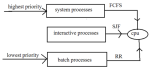
Starvation for low priority process
Multilevel feedback queue scheduling
Allows a process to move between queues. No starvation as processes moves to high priority queues as time quantum passes.
Process synchronization
The concurrent processes in an operating system are of two types:
Independent processes
An Independent process is a process that can not affect or be affected by the other processes. Independent processes do not share any data like temporary or persistent with any other process.Cooperating processes
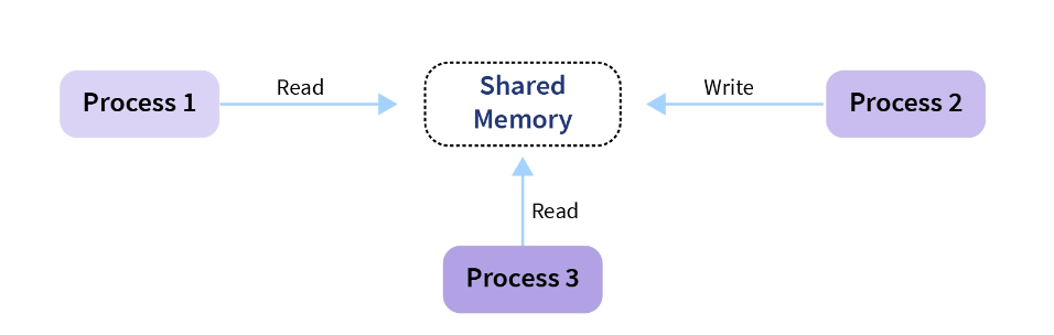
The cooperating process is affected or is affected by the other processes executing in the system. The cooperating process shares data with other processes.
If process1 is trying to read the data present in a memory location while process2 is trying to change the data present at the same location, there is a high chance that the data read by process1 will be incorrect.
Race condition-
When more than one process is either running the same code or modifying the same memory or any shared data, there is a risk that the result or value of the shared data may be incorrect because all processes try to access and modify this shared resource. Thus, all the processes race to say that my result is correct. This condition is called the race condition. Since many processes use the same data, the results of the processes may depend on the order of their execution.
Example:
Assume your current balance is ₹1000, and you add ₹200 from app A, and ₹500 from app B
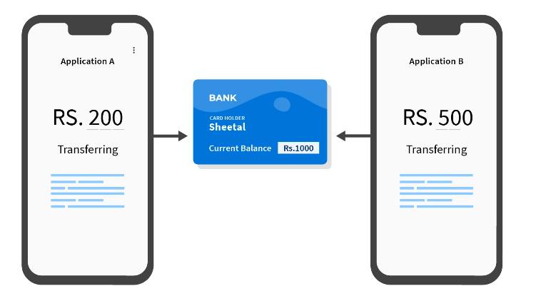
The following race condition occurs:
- App A reads the current balance, which is ₹1000
- App A adds ₹200 to ₹1000 and gets ₹1200 as the final balance
- Meanwhile, app B fetches the current balance, which is still ₹1000, as app A has not executed step 3
- App B adds ₹500 to ₹1000 and gets ₹1500 as the final balance
- App B updates the account balance to ₹1500
- App A updates the account balance to ₹1200
Thus the final balance is ₹1200 instead of ₹1700
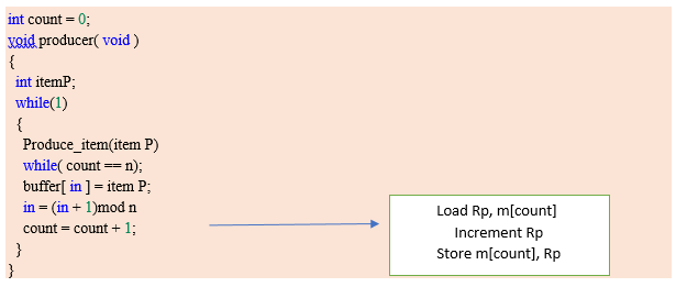
Producer consumer problem
There is one Producer in the producer-consumer problem, Producer is producing some items, whereas there is one Consumer that is consuming the items produced by the Producer. The same memory buffer is shared by both producers and consumers which is of fixed size.
The task of the Producer is to produce the item, put it into the memory buffer, and again start producing items. Whereas the task of the Consumer is to consume the item from the memory buffer.
Producer code:
Consumer code:
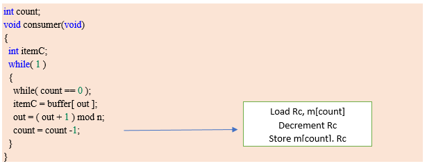
Race condition occurs here.
Critical section
The portion of the code in the program where shared variables are accessed and/or updated.
The critical section cannot be executed by more than one process at the same time; which can ensure that the Race condition among the processes will never arise.
A solution for the critical section problem must satisfy the following three conditions:
- Mutual exclusion
- Progress
- Bounded waiting
Mutual exclusion:
If a process Pi is executing in its critical section, then no other process is allowed to enter into the critical section.
Progress:
If no process is executing in the critical section, then the decision of a process to enter a critical section cannot be made by any other process that is executing in its remainder section. The selection of the process cannot be postponed indefinitely.
Bounded waiting:
We should be able to predict the waiting time for every process to get into the critical section. The process must not be endlessly waiting for getting into the critical section.
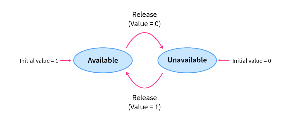
Lock variable mechanism
When Lock = 0 implies critical section is vacant (initial value ) and Lock = 1 implies critical section occupied.
The pseudocode looks something like this –
// Entry section
// acquire lock -
        while(lock != 0);
         Lock = 1;
// critical section
// release lock -
        Lock = 0;
// Exit section
❌ Mutual exclusion
Test and set lock mechanism
In the lock variable mechanism, Sometimes Process reads the old value of the lock variable and enters the critical section. Due to this reason, more than one process might get into the critical section.
To get rid of this problem, we have to make sure that the preemption must not take place just after loading the previous value of the lock variable and before setting it to 1. The problem can be solved if we can be able to merge the first two instructions.
In order to address the problem, the operating system provides a special instruction called Test Set Lock (TSL) instruction which simply loads the value of the lock variable into the local register R0 and sets it to 1 simultaneously.
//Shared variable lock initialized to false
boolean lock;

boolean TestAndSet (boolean &target){
    boolean r = target;
    target = true;
    return r;
}

while(1) {
    while (TestAndSet(lock));
    critical section
    lock = false;
    remainder section
}
✅ Mutual exclusion
✅ Progress
❌ Bounded wait
Semaphores
Semaphores are integer variables that are used to solve the critical section problem by using two atomic operations, wait and signal that is used for process synchronization.
P() or wait()
The wait operation decrements the value of its argument S if it is positive. If S is negative or zero, then no operation is performed.
wait(S)
{
   while (S<=0);

   S--;
}
V() or signal()
The signal operation increments the value of its argument S.
signal(S)
{
   S++;
}
Code-
Entry section - wait()
critical section
Exit section - signal()
There are two main types of semaphores i.e. counting semaphores and binary semaphores.
Counting Semaphores
These are integer value semaphores and have an unrestricted value domain. These semaphores are used to coordinate resource access, where the semaphore count is the number of available resources. If the resources are added, the semaphore count is automatically incremented and if the resources are removed, the count is decremented.'
Semaphore count is the number of resources available. If the value of the Semaphore is anywhere above 0, processes can access the critical section or the shared resources. The number of processes that can access the resources/code is the value of the semaphore. However, if the value is 0, it means that there aren't any resources that are available or the critical section is already being accessed by a number of processes and cannot be accessed by more processes. Counting semaphores are generally used when the number of instances of a resource is more than 1, and multiple processes can access the resource.
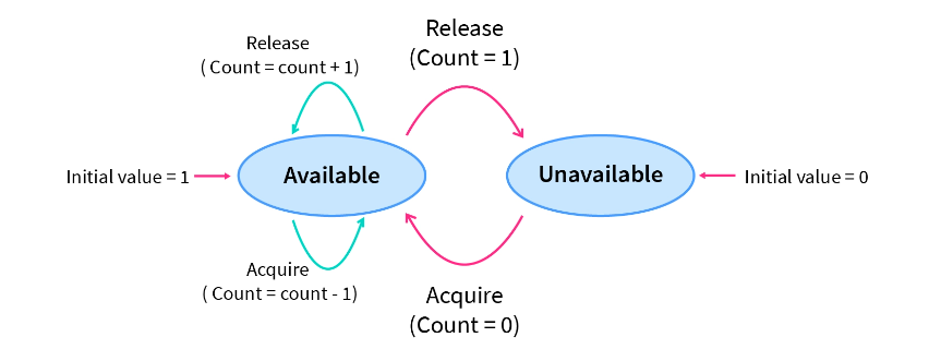
Binary Semaphores
The binary semaphores are like counting semaphores but their value is restricted to 0 and 1. The wait operation only works when the semaphore is 1 and the signal operation succeeds when the semaphore is 0.
Here, the integer value of the semaphore can only be either 0 or 1. If the value of the Semaphore is 1, it means that the process can proceed to the critical section (the common section that the processes need to access). However, if the value of the binary semaphore is 0, then the process cannot continue to the critical section of the code. When a process is using the critical section of the code, we change the Semaphore value to 0, and when a process is not using it, or we can allow a process to access the critical section, we change the value of the semaphore to 1. A binary semaphore is also called a mutex lock.
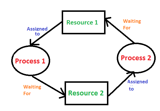
Deadlock
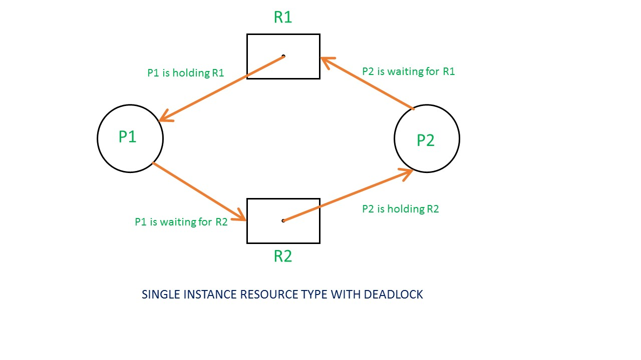
A situation where a set of processes are blocked because each process is holding a resource and waiting for another resource acquired by some other process. For example, Process 1 is holding Resource 1 and waiting for resource 2 which is acquired by process 2, and process 2 is waiting for resource 1.
Deadlock can arise if the following four conditions hold simultaneously (Necessary Conditions):
- Mutual Exclusion – One or more than one resource is non-sharable (Only one process can use at a time).
- Hold and Wait – A process is holding at least one resource and waiting for resources.
- No Preemption – A resource cannot be taken from a process unless the process releases the resource.
- Circular Wait – A set of processes are waiting for each other in circular form.
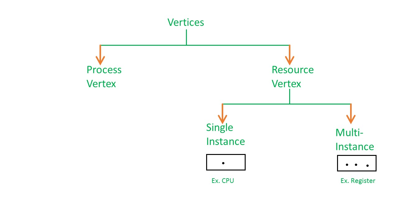
Resource allocation graph
In RAG vertices are of two types –
Process vertex –
Every process will be represented as a process vertex. Generally, the process will be represented with a circle.
Resource vertex –
Every resource will be represented as a resource vertex. It is also two type
- Single instance type resource: It is represented as a box, inside the box, there will be one dot. So the number of dots indicates how many instances are present of each resource type.
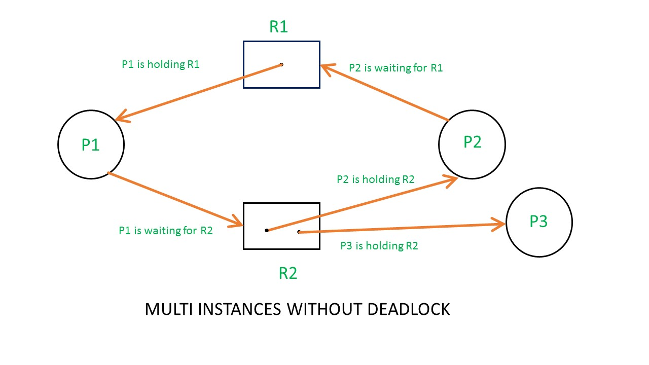
- Multi-resource instance type resource: It is also represented as a box, inside the box, there will be many dots present.
Note -
In a single instance RAG, if there is a cycle then deadlock exists and if a cycle is not present, then no deadlock exists.
In multi-instance RAG, if a deadlock exists then a cycle exists too but if a cycle exists in RAG then it is not necessary that deadlock exists.
i.e in the case of RAG with a multi-instance resource type, the cycle is a necessary condition for deadlock, but not sufficient.
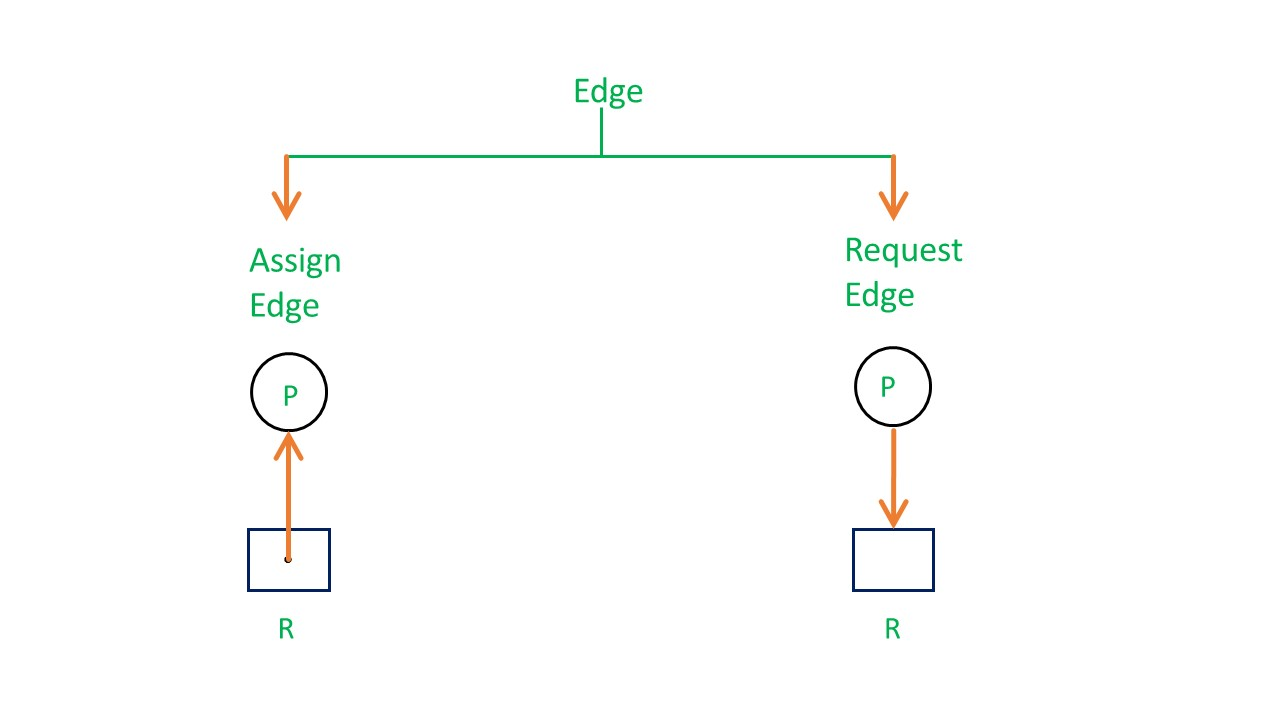
There are two types of edges in RAG –
Assign Edge –
If you already assign a resource to a process then it is called Assign edge.
Request Edge –
It means in the future the process might want some resources to complete the execution, which is called request edge.
Example of RAG:
Allocation matrix
For constructing the allocation matrix, just go to the resources and see to which process it is allocated.
Request matrix
In order to find out the request matrix, you have to go to the process and see the outgoing edges.
From the above example, it is not possible to say the RAG is in a safe state or in an unsafe state. So to see the state of this RAG, let’s construct the allocation matrix and request matrix.
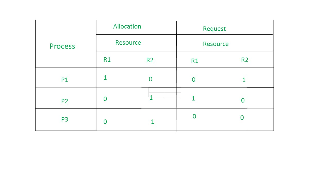
The available resources are (0,0)
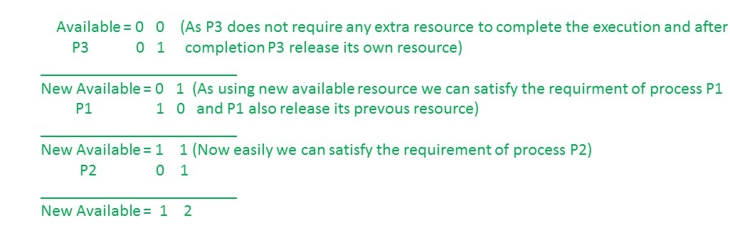
So, there is no deadlock in this RAG. Even though there is a cycle, still there is no deadlock.
Deadlock handling
Deadlock ignorance (Ostrich method)
Stick your head in the sand and pretend there is no problem at all, this method of solving any problem is called Ostrich Algorithm. This Ostrich algorithm is the most widely used technique in order to ignore the deadlock and also it used for all single end-users uses. If there is a deadlock in the system, then the OS will reboot the system in order to function well.
Deadlock prevention
There are 4 necessary conditions for deadlock-
- Mutual Exclusion
- Hold and Wait
- No preemption
- Circular wait
We can prevent Deadlock by eliminating any of the above four conditions.
Eliminate Mutual Exclusion
It is not possible to dis-satisfy the mutual exclusion because some resources, such as the tape drive and printer, are inherently non-shareable.
Eliminate No Preemption
Preempt resources from the process when resources are required by other high-priority processes.
Eliminate hold and wait
Allocate all required resources to the process before the start of its execution, this way hold and wait condition is eliminated but it will lead to low device utilization. for example, if a process requires a printer at a later time and we have allocated printer before the start of its execution printer will remain blocked till it has completed its execution.
Eliminate Circular Wait
Each resource will be assigned a numerical number. A process can request the resources increasing/ decreasing order of numbering.
For Example, if P1 process is allocated R5 resources, now next time if P1 ask for R4, R3 lesser than R5 such request will not be granted, only request for resources more than R5 will be granted.
Deadlock detection and recovery
Firstly, detect deadlock using the RAG graph.
Now, deadlock recovery by either killing the process or resource preemption.
Killing the process:
Killing all the processes involved in the deadlock. Killing process one by one. After killing each process check for deadlock again and keep repeating the process till the system recovers from deadlock. Killing all the processes one by one helps a system to break the circular wait condition.Resource Preemption:
Resources are preempted from the processes involved in the deadlock, preempted resources are allocated to other processes so that there is a possibility of recovering the system from deadlock. In this case, the system goes into starvation.
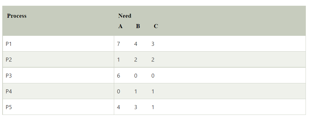
Deadlock avoidance (Bankers Algorithm)
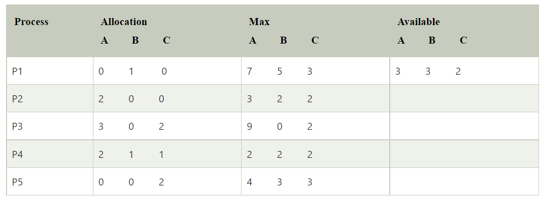
Need matrix -
Available Resources of A, B, and C are 3, 3, and 2.
Step 1: For Process P1:
Need <= Available
7, 4, 3 <= 3, 3, 2 condition is false.
So, we examine another process, P2.Step 2: For Process P2:
Need <= Available
1, 2, 2 <= 3, 3, 2 condition true
New available = available + Allocation
(3, 3, 2) + (2, 0, 0) => 5, 3, 2
Similarly, we examine another process P3.Step 3: For Process P3:
P3 Need <= Available
6, 0, 0 < = 5, 3, 2 condition is false.
Similarly, we examine another process, P4.Step 4: For Process P4:
P4 Need <= Available
0, 1, 1 <= 5, 3, 2 condition is true
New Available resource = Available + Allocation
5, 3, 2 + 2, 1, 1 => 7, 4, 3
Similarly, we examine another process P5.Step 5: For Process P5:
P5 Need <= Available
4, 3, 1 <= 7, 4, 3 condition is true
New available resource = Available + Allocation
7, 4, 3 + 0, 0, 2 => 7, 4, 5
Now, we again examine each type of resource request for processes P1 and P3.Step 6: For Process P1:
P1 Need <= Available
7, 4, 3 <= 7, 4, 5 condition is true
New Available Resource = Available + Allocation
7, 4, 5 + 0, 1, 0 => 7, 5, 5
So, we examine another process P2.Step 7: For Process P3:
P3 Need <= Available
6, 0, 0 <= 7, 5, 5 condition is true
New Available Resource = Available + Allocation
7, 5, 5 + 3, 0, 2 => 10, 5, 7
Hence, we execute the banker's algorithm to find the safe state and the safe sequence like P2, P4, P5, P1, and P3.
Memory management
Allow the memory to be shared among multiple processes
In a multiprogramming computer, the operating system resides in a part of memory and the rest is used by multiple processes. The task of subdividing the memory among different processes is called memory management.
Why Memory Management is required:
- Allocate and de-allocate memory before and after process execution.
- To keep track of used memory space by processes.
- To minimize fragmentation issues.
- To proper utilization of main memory.
- To maintain data integrity while executing of process.
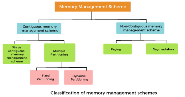
Single contiguous memory management
In this scheme, the main memory is divided into two contiguous areas or partitions. The operating systems reside permanently in one partition, generally at the lower memory, and the user process is loaded into the other partition.
Fixed partitioning (Static partition)
The main memory is divided into several fixed-sized partitions in a fixed partition memory management scheme or static partitioning. These partitions can be of the same size or different sizes. Each partition can hold a single process. The number of partitions determines the degree of multiprogramming, i.e., the maximum number of processes in memory. These partitions are made at the time of system generation and remain fixed after that.
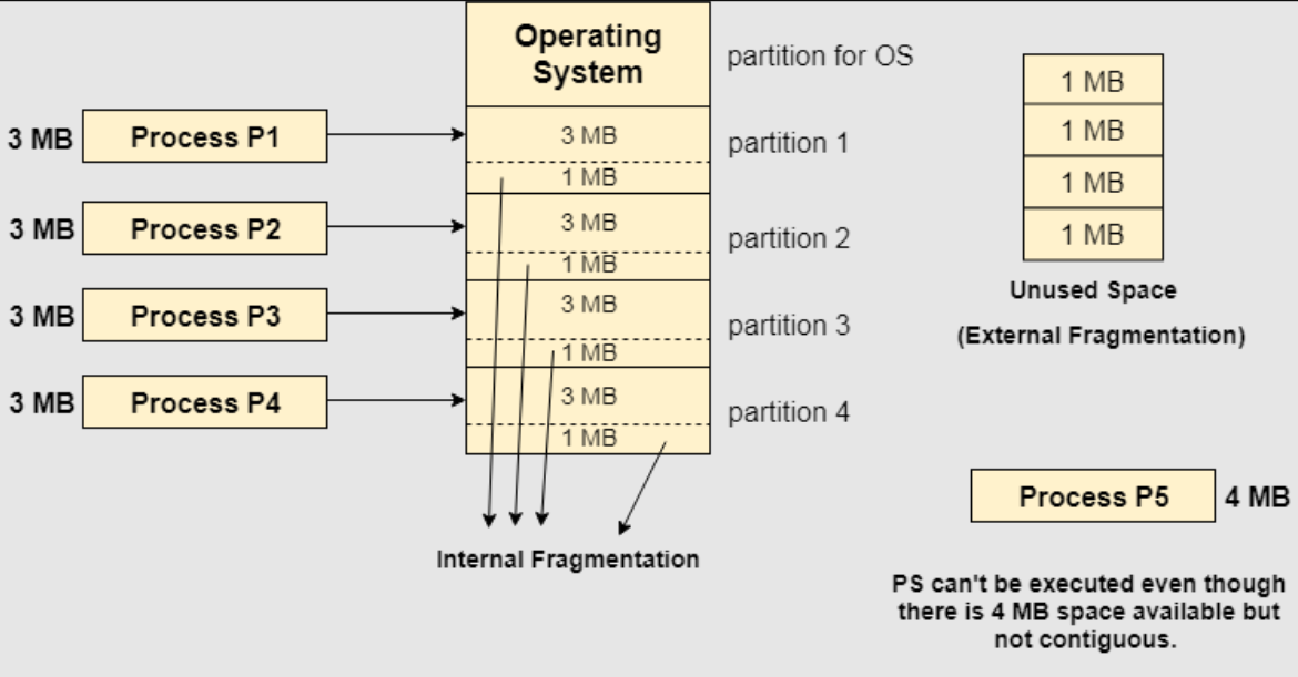
Suffers from internal fragmentation as well as external fragmentation.
Only fixed no of processes can be brought to main memory at a time.
Variable partitioning (Dynamic partition)
In a dynamic partitioning scheme, each process occupies only as much memory as they require when loaded for processing. Requested processes are allocated memory until the entire physical memory is exhausted or the remaining space is insufficient to hold the requesting process. In this scheme the partitions used are of variable size, and the number of partitions is not defined at the system generation time.
No internal fragmentation
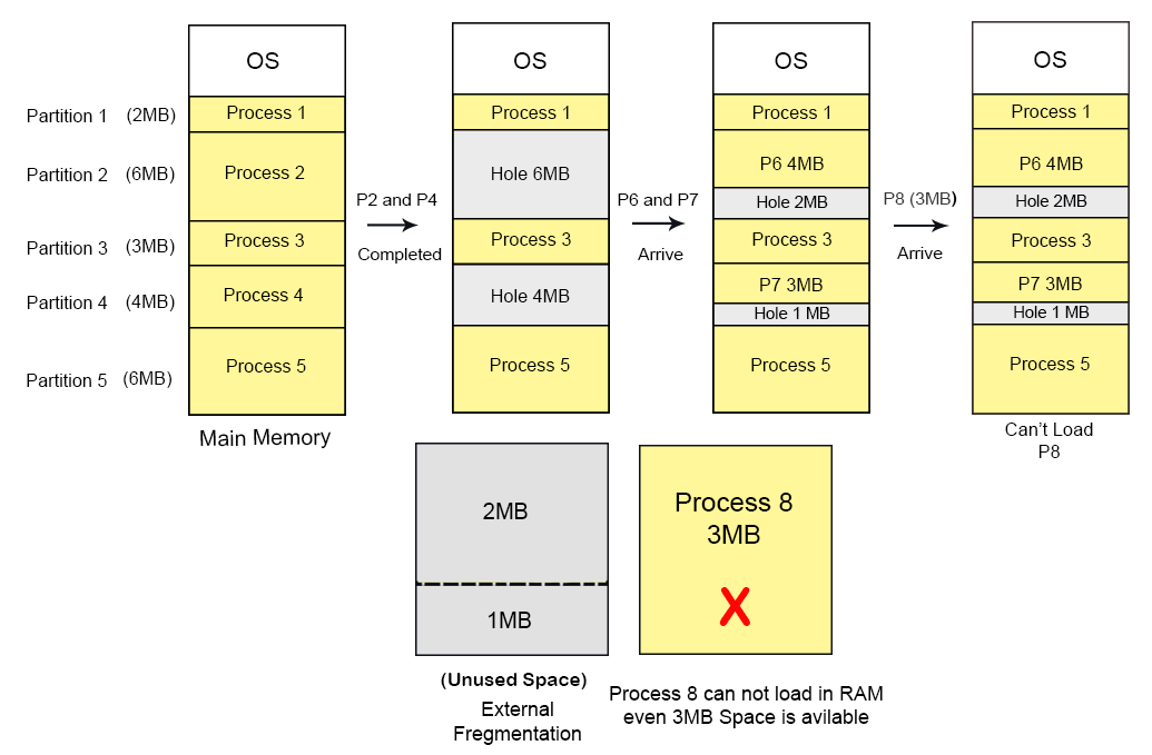
Suffers from external fragmentation
Variable partition allocation schemes:
First fit
The arriving process is allotted the first hole of memory in which it fits completely.
Best fit
The arriving process is allotted the hole of memory in which it fits the best by leaving the minimum memory empty.
Worst fit
The arriving process is allotted the hole of memory in which it leaves the maximum gap.
Paging
The cause of external fragmentation is the condition in Fixed partitioning and Variable partitioning saying that the entire process should be allocated in a contiguous memory location. Therefore Paging is used.
In paging -
The physical memory is divided into equal-sized frames. The main memory is divided into fixed-size pages. The size of a physical memory frame is equal to the size of a virtual memory frame.
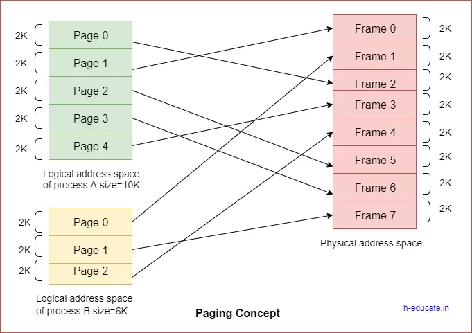
Page table
A page table is the data structure used by a virtual memory system in a computer operating system to store the mapping between virtual addresses and physical addresses.
Page fault
A page fault is a type of interrupt, raised by the hardware when a running program accesses a memory page that is mapped into the virtual address space, but not loaded in physical memory.
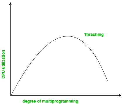
Thrashing
Thrashing is a condition or a situation when the system is spending a major portion of its time servicing the page faults, but the actual processing done is very negligible.
When the CPU’s usage is low, the process scheduling mechanism tries to load multiple processes into memory at the same time, increasing the degree of Multiprogramming.
In this case, the number of processes in the memory exceeds the number of frames available in the memory. Each process is given a set number of frames to work with.
If a high-priority process arrives in memory and the frame is not vacant at the moment, the other process occupying the frame will be moved to secondary storage, and the free frame will be allotted to a higher-priority process.
We may also argue that as soon as the memory is full, the procedure begins to take a long time to swap in the required pages. Because most of the processes are waiting for pages, the CPU utilization drops again.
As a result, a high level of multiprogramming and a lack of frames are two of the most common reasons for thrashing in the operating system.
Segmentation
Segmentation is a memory management technique in which each job is divided into several segments of different sizes, one for each module that contains pieces that perform related functions.
Page replacement algorithms
The page replacement algorithm decides which memory page is to be replaced. Page replacement is done when the requested page is not found in the main memory (page fault).
First in First Out (FIFO)
In this algorithm, a queue is maintained. The page which is assigned the frame first will be replaced first. In other words, the page which resides at the rare end of the queue will be replaced on every page fault.
- Belady’s anomaly:
Belady’s anomaly proves that it is possible to have more page faults when increasing the number of page frames while using the First in First Out (FIFO) page replacement algorithm. For example, if we consider reference string 3 2 1 0 3 2 4 3 2 1 0 4 and 3 slots, we get 9 total page faults, but if we increase slots to 4, we get 10 page faults.
Optimal page replacement
In this algorithm, pages are replaced which are not used for the longest duration of time in the future.
Optimal page replacement is perfect, but not possible in practice as an operating system cannot know future requests. The use of Optimal Page replacement is to set up a benchmark so that other replacement algorithms can be analyzed against it.
Least recently used (LRU)
In this algorithm, the page will be replaced which is least recently used i.e replaces the page which has not been referred to for a long time.
Disk scheduling
Disk scheduling is important because:
- Multiple I/O requests may arrive by different processes and only one I/O request can be served at a time by the disk controller. Thus other I/O requests need to wait in the waiting queue and need to be scheduled.
- Two or more request may be far from each other so can result in greater disk arm movement.
- Hard drives are one of the slowest parts of the computer system and thus need to be accessed in an efficient manner.
Disk architecture: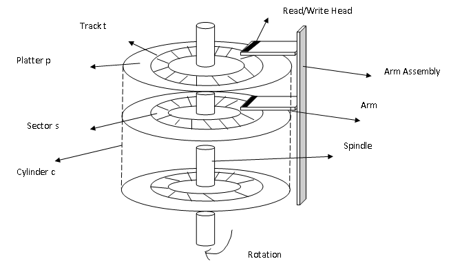
Seek Time:
Seek time is the time taken to locate the disk arm to a specified track where the data is to be read or write.
Rotational Latency:
Rotational Latency is the time taken by the desired sector of disk to rotate into a position so that it can access the read/write heads.
Transfer Time:
Transfer time is the time to transfer the data. It depends on the rotating speed of the disk and the number of bytes to be transferred.
Disk Access Time:
Seek Time + Rotational Latency + Transfer Time
Disk Response Time:
Response Time is the average of time spent by a request waiting to perform its I/O operation. Average Response time is the response time of all requests.
Disk scheduling algorithms
FCFS
In FCFS, the requests are addressed in the order they arrive in the disk queue.
SSTF
In SSTF (Shortest Seek Time First), requests having the shortest seek time are executed first. So, the seek time of every request is calculated in advance in a queue and then they are scheduled according to their calculated seek time. As a result, the request near the disk arm will get executed first.
SCAN
In the SCAN algorithm, the disk arm moves into a particular direction and services the requests coming in its path and after reaching the end of the disk, it reverses its direction and again services the request arriving in its path. So, this algorithm works like an elevator and is hence also known as the elevator algorithm.


